
Five Decades Later: Integrating Technology in a Large, Lecture Hall
Rebecca Gould, Kansas State University
Background
Evolution of Learning Spaces
Dilemma
Process and Timeline
Key Players and Their Roles
Challenges
Renovation
Technology
Lessons Learned
Continuous Improvement
The guiding principles for decisions in our classrooms are to meet the goals outlined by the faculty and students, to standardize technology across rooms, to provide an environment that is sustainable and to focus on ease of use. The complexity of hardware to support a room may be great; however, what faculty need to drive the room is simple. Again, we refer to this as the one button to push approach.
To address the interactivity and distance issue, the room was reoriented by 90 degrees to reduce the distance from student to faculty to less than half of existing distance. A complex new sloping floor configuration (Tate Access Floor, Inc.) improved load limitations and concealed the original stage. The seating capacity was reduced from 483 to 450, which included six spaces for accessibility, located in both the front and back of the room. Seating went from 18'' to 21-22'' width, and work surface became 247 square inches. Pre- and post-renovation room specifications are provided in Table 3 (see below). A panoramic view of renovations after the floor was installed is provided in Figure 12.
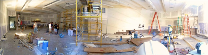
Figure 12. Interior construction of the classroom: This panoramic view of Umberger 105 was taken after the installation of the pedestal floors. Workers had installed dry wall and were touching up the ceiling.
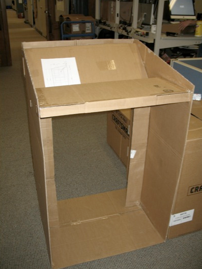
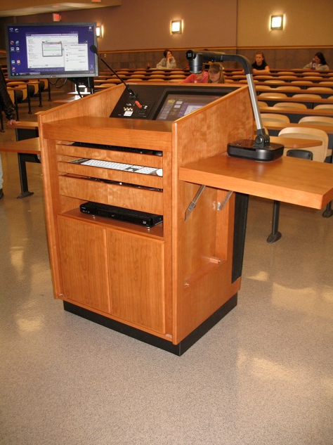
A student in the Interior Architecture and Product Design program designed the podium using RevittTM, mocking up the podium in cardboard (Figure 13) and then asking the faculty to test drive the mock up. Tweaks were made based on faculty input and then built by a local company (Figures 14, 15).
 |
 |
 |
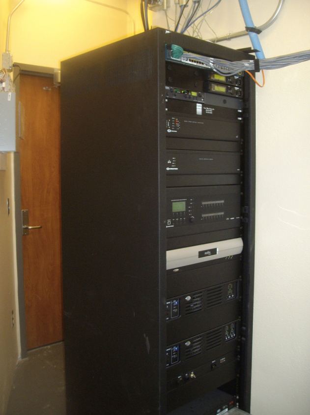 |
Figure 13. Umberger 105 Podium mock-up: The podium, designed by a student in interior architecture, was first created on paper and then built to scale using cardboard and tape. Faculty were invited to test drive the cardboard podium and make suggestions for improvements. |
Figure 14. Podium: Front view of podium depicting controls, drop down shelf, confidence monitor and visual presenter. |
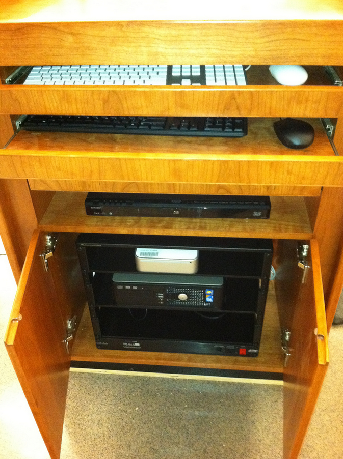
Figure 15. Podium: Interior view of the podium showing keyboard shelves, and open cabinets with limited technology. The majority of the podium is located in the technology closet at the back of the room. |
Figure 16. Network and telecom equipment room: The major rack with equipment was located in the southern end of the room for ease of access and serviceability. |
This podium design has been tweaked and used in other venues on campus. Space for technology was built in the southwest corner of the room, to reduce the equipment in the podium and, when the need for tech support arose, limit disruption during class time (Figure 16).
Comparison of Pre- and Post-Renovation Room Specifications
|
Pre-Renovation |
Post-Renovation |
Seating Capacity |
483 |
450 |
| Seat Width | 18 Inches | 21-22 Inches |
| Accessible Seating | Rear only | Front and rear |
| Work Surface | 117 Square Inches | 247 Square Inches |
| Average View Distance | 58 Feet | 27 Feet |